
Industries
Tower Monitoring Systems for Unmanned Transmitter Sites
Remote monitoring for telecommunications towers, broadcast and cell sites — RF power, batteries, rectifiers, generators, environment and site access, measured continuously and reported before a fault becomes an outage.
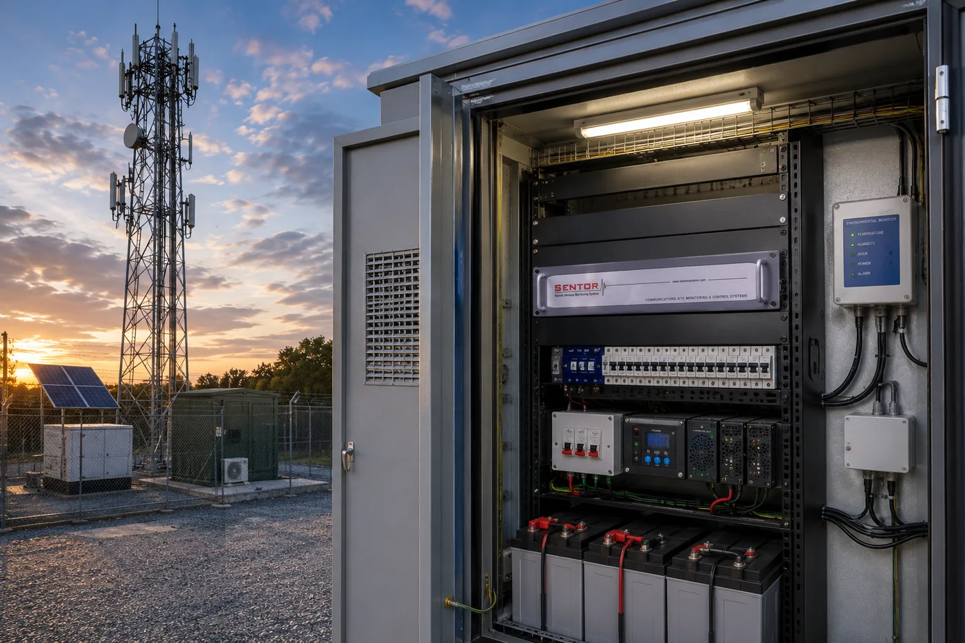
The problem
Tower sites fail quietly. A rectifier drops and the batteries begin to carry the load. Reflected power creeps up as water finds its way into a connector. An air conditioner stops and the shelter temperature climbs through the afternoon. None of these announce themselves, and at an unmanned site there is nobody to notice. The first sign is usually a customer complaint or a dropped service — hours or days after the condition began, by which time the cheap fix has become an emergency call-out to a site that may be several hours away.
How Sentor solves it
A Sentor controller at the site measures those conditions continuously and decides, on site, what they mean. Forward and reflected power, battery voltage, rectifier and generator status, shelter temperature, door position and mains supply are all read as ordinary electrical signals — contact closures, voltages and current loops that the equipment already produces. Scenario logic stored on the controller compares them against the thresholds set for that site and acts: raising an alarm, operating a relay, and writing the event to a log with a time and date stamp.
What Sentor monitors
Monitored and controlled at a tower or broadcast site
Everything below is read as an ordinary electrical signal from equipment already installed at the site.
- Forward and reflected power (VSWR) per transmitter or antenna
- Received signal strength, where the radio provides an analogue output
- Battery string voltage and charge state
- Rectifier and charger status
- Mains supply and phase failure
- Generator run, fail-to-start and fault contacts
- Fuel level, through a tank sender on an analogue input
- Shelter temperature and humidity
- Air conditioner run and fault status
- Door position and tamper detection
- Site access by card, keypad or biometric reader
- Obstruction lighting fault contacts, where the lighting controller provides one
Signals
What connects, and what it tells you
Tower sites are full of equipment that already reports its own condition. Most of it needs no gateway and no protocol conversation — just a pair of wires to the right kind of input.
| Signal | How it connects | What it tells you |
|---|---|---|
| Forward and reflected power | ST505 bi-directional coupler, two analogue inputs per transmitter | A rising reflected figure is the earliest sign of a feeder, connector or antenna fault |
| Battery voltage | Analogue input, 0–30 V DC range | Shows the string carrying load before it reaches the point of dropping the site |
| Rectifier / charger status | Clean contact closure on a digital input | Distinguishes a charger fault from a mains failure |
| Mains and generator | Run, fail and fault contacts on digital inputs | Separates an expected exercise run from a failure to start |
| Fuel level | Tank sender on a 4–20 mA or voltage input | Refuelling is scheduled on a reading rather than a calendar |
| Shelter temperature | ST025 or ST025E temperature sensor | Catches an air-conditioning failure while the equipment is still within rating |
| Door and tamper | Contact and tamper input on the controller | Every opening is logged, whether or not anyone reported the visit |
| Site access | ST352A Wiegand interface, keypad or biometric reader | Entry and exit recorded against the card used, at every site on one list |
RF performance
Reflected power is the measurement that pays for itself
Most site faults announce themselves eventually. A feeder problem does not — it degrades slowly, costs coverage the whole time, and is usually found only when someone climbs the tower for another reason.
Because the coupler reports forward and reflected power as continuous analogue readings rather than a simple alarm contact, the controller logs a trend rather than an event. A technician arrives knowing which antenna, how far it has moved and over what period, instead of arriving to investigate. That trend history is also what makes the reading usable in compliance reporting, where the question is what the site has been doing, not what it is doing right now.
ST505 bi-directional coupler
Real-time forward and reflected power (VSWR) in watts or dBm. Almost zero insertion loss, non-invasive, pre-calibrated to frequency, male or female N connectors. Fitted in line on the coaxial feeder and read on two analogue inputs.
When the link drops
A tower site that cannot phone home still has to run itself
This is the difference between a monitoring system and a telemetry link. Sentor stores its decision-making on the controller at the site, as scenario logic written in plain if-this-then-that terms. If the cellular service fails, or the microwave path drops, or the backhaul is cut, the site keeps measuring, keeps acting on what it measures and keeps logging — and hands over the record when the link comes back.
It matters most in exactly the situation you would least want it to matter: a mains failure that takes the backhaul with it, leaving the site on batteries with nobody able to see it.
Common questions
Tower site monitoring, answered
How is forward and reflected power actually measured?
An ST505 bi-directional coupler is fitted in line on the coaxial feeder. It is non-invasive with almost zero insertion loss, is pre-calibrated to frequency, and is supplied with male or female N connectors. It presents forward and reflected power as two analogue signals, reported in watts or dBm. Each input is conditioned through a calibration curve of the form Ax² + Bx + C, and Sentor supplies the utility that calculates those coefficients during commissioning, so the figure the controller reports is the figure at the feeder.
What happens if the site loses its connection back to base?
Nothing at the site changes. Scenario logic is stored on the controller, not in the software at the other end of the link, so the site continues to measure, decide and act while it is offline. Events are written to the on-board history log with a time and date stamp and are there when the link returns. The connection governs how quickly you hear about something — not whether the site handles it.
How many transmitters can one controller cover?
Each coupler uses two analogue inputs, one forward and one reflected. The base controller’s analogue inputs are extended by ST317 expansion cards, each adding eight analogue inputs, eight digital inputs and eight optional digital outputs. How many transmitters a single controller covers therefore depends on what else is being monitored at the same site. Send us the signal list and we will tell you exactly what it takes.
How does an unmanned tower site report back?
Whichever bearer reaches it. The ST30G provides always-on multi-band 3G/4G with a static IP address and SSL-encrypted access. Where there is no cellular coverage, the ST303 RF modem serves the site over radio. The ST330 adds a landline path with voice alarm calls and DTMF keypad control. Different sites on the same network can use different methods, and the controller behaves identically either way.
Can a transmitter be changed or reset remotely?
Yes. Relay outputs on the controller operate equipment directly, and an authorised operator can trigger them from SitePRO or SentorCloud, or over a voice call through the ST330. The controller checks the programmed conditions before acting, so an interlock is respected regardless of who asked, and the action is written to the event log against the time it happened.
Recommended configuration
- ST3000 or i7000 controller (rack or wall mount)
- ST505 bi-directional coupler per transmitter
- ST317 expansion cards for additional I/O
- ST30G cellular, ST303 radio or ST330 landline
- SitePRO, SenTrend and SentorCloud software
Key benefits
- Fewer emergency site visits
- Faster fault isolation
- VSWR trend history for compliance reporting
- One dashboard across a whole tower network
Related